Ballistic Shock Defined
Ballistic Shock is a high-level shock that generally results from the impact of projectiles or ordnance on armored combat vehicles. Armored combat vehicles must survive the shocks resulting from large caliber non-perforating projectile impacts, mine blasts, and overhead artillery attacks, while still retaining their combat mission capabilities. This is a very complex subject given actual shock levels vary with the type of vehicle, the specific munition used, the impact location or proximity, and where on the vehicle the shock is measured. No good computational simulation has yet been developed. That is, the prediction of response to ballistic shock is, in general, not possible except in the simplest configurations. When an armored vehicle is subjected to a non-perforating large caliber munition impact or blast, the structure locally experiences a force loading of very high intensity and of relatively short duration. Though the force loading is localized, the entire vehicle is subjected to stress waves traveling over the surface and through the structure.
General characteristics of ballistic shock environments are as follows:
- near-the-source stress waves in the structure caused by high material strain rates (nonlinear material region) that propagate into the near field and beyond;
- combined low and high frequency (10 Hz – 1,000,000 Hz) and very broadband frequency input;
- high acceleration (300g – 1,000,000g) with comparatively high structural velocity and displacement response;
- short-time duration (<180 msec);
- high residual structure displacement, velocity, and acceleration response (after the event);
- caused by (1) an inelastic collision of two elastic bodies, or (2) an extremely high fluid pressure applied for a short period of time to an elastic body surface coupled directly into the structure, and with point source input, i.e., input is either highly localized as in the case of collision, or area source input, i.e., widely dispersed as in the case of a pressure wave;
- comparatively high structural driving point impedance (P/v, where P is the collision force or pressure, and v the structural velocity). At the source, the impedance could be substantially less if the material particle velocity is high;
- measurement response time histories that are very highly random in nature, i.e., little repeatability and very dependent on the configuration details;
- shock response at points on the structure is somewhat affected by structural discontinuities;
- structural response may be accompanied by heat generated by the inelastic impact or the fluid blast wave;
- the nature of the structural response to ballistic shock does not suggest that the materiel or its components may be easily classified as being in the “near field” or “far field” of the ballistic shock device. In general, materiel close to the source experiences high accelerations at high frequencies, whereas materiel far from the source will, in general, experience high acceleration at low frequencies as a result of the filtering of the intervening structural configuration.
Effects of Ballistic Shock
- system failure as a result of destruction of the structural integrity of micro electronic chips including their mounting configuration;
- system component failure as a result of relay chatter;
- system component failure as a result of circuit card malfunction, circuit card damage, and electronic connector failure. On occasion, circuit card contaminants having the potential to cause short circuits may be dislodged under ballistic shock. Circuit card mounts may be subject to damage from substantial velocity changes and large displacements.
- material failure as a result of cracks and fracture in crystals, ceramics, epoxies or glass envelopes.
- system component failure as a result of sudden velocity change of the structural support of the system component, or the internal structural configuration of the mechanical or electro-mechanical system.
Selecting a Test Procedure
Method 522.1 provides for five ballistic shock tests:
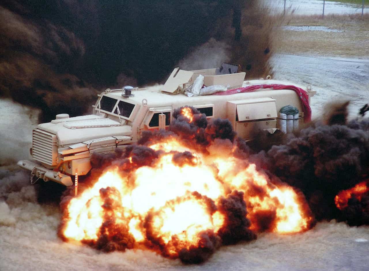
Procedure I – Ballistic Hull and Turret
Procure an actual vehicle or prototype and fire appropriate threat projectiles at it. This is a very expensive test.
Procedure II – Large Scale Ballistic Shock Simulator
Shock testing of complete components, with assemblies weighing up to 1100 lbs, can be accomplished using devices such as a Large Scale Ballistic Shock Simulator. For large items, the Large Scale Ballistic Shock Simulator (LSBSS) utilizes an explosive charge to drive a plate to which the materiel is mounted. This is considerably less expensive than Procedure I.
Procedure III – Light Weight Shock Machine
For assemblies weighing less that 250 lbs, a Light Weight Shock Machine from MIL-S-901D can be used.
Procedure IV – Mechanical Shock Simulator
Mechanical shock simulators have been constructed to test very light weight components (1 to 4 lb) for the smallest machine; higher for other contractor machines.
Procedure V – Medium Weight Shock Machine
For assemblies weighing less that 5000 lbs, a Medium Weight Shock Machine from MIL-S-901D can be used.
Procedure VI – Drop Table
Light weight components, usually weighing less than 40 lbs, can be tested using a drop table. The commonly available drop test machine is the least expensive and most accessible test technique.
Test Evaluation
After the testing, evaluate the components for damage and proper operation.