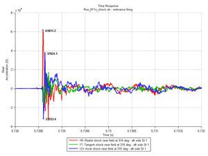
 MIL-STD-810G covers Pyroshock in Method 517.1. Pyroshock is a high intensity, short duration shock event caused by the detonation of a pyrotechnic device on adjacent structures. Pyroshock is a physical phenomenon characterized by the overall material and mechanical response at a structure point from either (a) an explosive device, or (b) a propellant activated device. Method 517.1 is comprised of 23 pages. Method 517.1 is not intended to test material exposed to external explosions. Use this method to evaluate materiel likely to be exposed to one or more pyroshocks in its lifetime. In general, the pyroshock sources may be described in terms of their spatial distribution – point sources, line sources and combined point and line sources. Point sources include explosive bolts, separation nuts, pin pullers and pushers, bolt and cable cutters and pyro-activated operational hardware. Line sources include flexible linear shape charges (FLSC), mild detonating fuses (MDF), and explosive transfer lines. Combined point and line sources include V-band (Marmon) clamps. Pyroshocks are generally within a frequency range between 100 Hz and 1,000,000 Hz, and a time duration from 50 microseconds to not more than 20 milliseconds. Acceleration response amplitudes to pyroshock may range from 300 g to 300,000 g. Pyroshock usually exhibits no momentum exchange between two bodies (a possible exception is the transfer of strain energy from stress wave propagation from a device through structure to the materiel). Pyroshock results in essentially no velocity change in the materiel support structure. The characteristics of pyroshock are:
- near-the-source stress waves in the structure caused by high material strain rates (nonlinear material region) propagate into the near-field and beyond;
- high frequency (100 Hz to 1,000,000 Hz) and very broadband frequency input;
- high acceleration (300 g to 300,000 g) but low structural velocity and displacement response;
- short-time duration (< 20 msec);
- high residual structure acceleration response (after the event);
- caused by (1) an explosive device or (2) a propellant activated device (releasing stored strain energy) coupled directly into the structure; (for clarification, a propellant activated device includes items such as a clamp that releases strain energy causing a structure response greater than that obtained from the propellant detonation alone);
- highly localized point source input or line source input;
- very high structural driving point impedance (P/v, where P is the large detonation force or pressure, and v, the structural velocity, is very small). At the pyrotechnic source, the driving point impedance can be substantially less if the structure material particle velocity is high;
- response time histories that are random in nature, providing little repeatability and substantial dependency on the materiel configuration details;
- response at points on the structure that are greatly affected by structural discontinuities;
- materiel and structural response that may be accompanied by substantial heat and electromagnetic emission (from ionization of gases during explosion).
Examples of electronic problems associated with pyroshock follow, but the list is not intended to be all-inclusive.
- materiel failure as a result of destruction of the structural integrity of microelectronic chips;
- materiel failure as a result of relay chatter;
- materiel failure as a result of circuit card malfunction, circuit card damage, and electronic connector failure. On occasion, circuit card contaminants having the potential to cause short circuits may be dislodged under pyroshock.
- materiel failure as a result of cracks and fracture in crystals, ceramics, epoxies, or glass envelopes.
