Cooling and Noise in Industrial and Military Computer Systems
This White Paper provides generalized information on chassis cooling, noise generation and fan failure issues for industrial computers.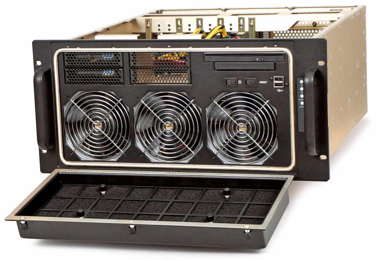
- Introduction
- Fan Flow Rate
- Chassis Temperature Rise From Installed Cards
- Chassis Air Flow Impedance Curve
- Fans versus Blowers
- Example Data for Model 417-MB Chassis
- Fan Operation at High Altitudes
- Fan Manufacturer Resources
- Chassis Noise
- Fan Failure Detection
1. Introduction
One of the main differences between an industrial computer and an office clone computer is cooling. Industrial computers typically provide between one and four fans pulling through air filters in addition to the fan in the power supply. The typical office clone computer simply uses the one small fan in the power supply for cooling. Industrial computers provide a positive chassis pressure to control dust entry. Clone computers run at a negative internal pressure and become very dusty inside. If high ambient temperatures or noise are not an issue, you can skip this section. Otherwise, the following information will demonstrate the maximum ambient temperature any industrial chassis can safely operate in as well as help with chassis noise reduction. You will see most manufacturers’ operating temperature and power supply specifications are unrealistic and not supportable. Additional cooling allows for higher power boards to be installed plus extends component life by limiting the maximum temperatures the components are exposed to. In general, a 10 deg C temperature reduction will provide a 2:1 increase in MTBF. There are two methods for selecting a fan. The first is to simply install as many of the biggest fans available as will fit. This works well if cost and noise are not factors. In general, a single fan, regardless of size, will cost about $20 with installation, grills, etc. A 4-½” fan will cost about $5 more than a 3-½” fan. This is not significant compared to the total system cost. However, four fans will cost about $80 or 25% of the chassis cost but a small percentage of the integrated system cost. System cooling performance should be determined to assure cards are not operated above their published temperature limits. However, noise is often a limiting factor for chassis selection with conflicting requirements for operating temperature versus low noise generation. This is becoming more pronounced with the high speed processors such as dual Xeon which require 200Watts just for the motherboard. We are seeing more specifications that include a noise limit for normal operation. A single chassis doesn’t seem very loud. But if you package six chassis in a rack and put several racks in a room, the combined noise can be deafening. The problem with bigger fans is they generate significantly more noise than smaller fans. “Bigger” used in this context refers to the speed and free air flow rating of the fan. Often, the bigger fan is simply stirring the air and providing no real additional cooling benefit. Because the chassis pressure impedance curve (pressure required to move air) is nonlinear, doubling fan capacity does not double the air delivery. Fans that are physically larger typically are more quiet because you can get the same volume of air flow with a lower fan RPM. Its the RPM that generates the noise. Please keep in mind the following discussion is directed at applications where noise is of some concern. If noise is not a limiting factor, then installing fans with the most flow will assure the lowest internal temperatures and longest component life. However, every chassis has a maximum allowed power loading that can easily be calculated. For the most part, all industrial computer chassis are constructed the same way with very similar layouts. This discussion will apply to any of these chassis. You should ask your potential supplier for a copy of their chassis impedance plot to determine actual chassis cooling performance in the intended environment.2. Fan Flow Rate
Cooling fan selection for an industrial chassis is very straightforward. Installed boards generate heat that must be removed from the chassis. The maximum allowable internal chassis temperature is determined by the component with the lowest operating temperature specification. The temperature rise inside a chassis will be a constant factor depending only on the installed boards. This means the installed boards generate a temperature rise that is simply added to the inlet temperature to determine the temperature inside the chassis. Thus, if you measure the temperature inside a chassis at room temperature, the internal temperature will rise by the same amount as an external temperature rise. If your internal temperature is 100 deg F at an outside temperature of 70 deg F (30 deg internal rise), the internal temperature will be 150 deg F when the ambient temperature is 120 deg F. 150 deg F is generally well above published operating limits for installed drives and boards. This means you can easily measure the temperatures inside the chassis in your office at room temperature and then calculate what the internal temperature will be when the chassis is installed in the field. The one caveat to this is fans are less efficient at higher temperatures because the air density is lower at higher temperatures. Thus a given fan will move less air at an elevated temperature. If your calculations show a marginal condition at the expected operating temperature, then you should measure the actual internal temperatures with the chassis operating at an elevated external temperature. Power is power. There is no difference between digital heat and resistive heat. A system with a 300 watt power supply at full capacity is generating 300 watts of heat. In addition, the power supply is generating additional heat because of it’s inherent inefficiency. Power supplies are usually about 70-75% efficient, so a 300 watt supply at full load generates 416 watts of heat. As a comparison, think of your 1000 watt hair dryer. For UL certification, a chassis will have resistive load resistors installed on each of the power supply outputs with the load equal to the rated output. Thus there will be 300 watts of heat generated inside the chassis. An important consideration in this discussion is UL and other safety agency ratings. UL will require a system be tested at the full power supply rating and at the rated maximum operating temperature. You can see from the following discussion that the internal chassis temperature will exceed the rating for the power supply and the chassis will fail the UL testing. The only alternative is to specify a limited high ambient temperature or derate the power supply. The amount of required air is dependent on the heat generated by the installed cards, the temperature of the inlet cooling air, and the maximum internal temperature allowed. Any particular fan will only move so much air through a chassis limited by the chassis flow resistance. One item that has a tremendous effect on the system resistance is the air filter. If your application is in a relatively clean environment, you probably don’t need an air filter. On the other hand, if there is conductive dust floating about, you want to keep that out of the chassis. You should choose an air filter based on what you are trying to filter, the available maintenance, and allowable resistance. See Universal Air Filter for information on various filter media. One last item to keep in mind is the location in the chassis of the heat generating components. Assuming relatively smooth flow through a chassis, the air temperature will rise as it passes hot components. Thus, if the processors are located at the front of the chassis, any component down stream will be immersed in hot air. Conversely, if the processors are at the rear of the chassis, most of their heat is exhausted directly out of the chassis. The actual temperature rise of the air as calculated below is the exit air temperature. Thus, sensitive components, such as drives, should be placed upstream of the heat generating components. On the other hand, the new high speed drives can be some of the worse offenders in generating heat. The location of the power supply should be carefully considered. If it is mounted internally, in the front of the chassis, for example, the inefficiency of the supply will blow pre-heated air into the other components. High efficiency power supplies are only 80% efficient. Thus, for a 600W system, the supply will generate an additional 120W of waste heat. It is best to exhaust this heat directly out of the chassis. A good alternative to heat control is exhibited by our XPT Single Board Computer with dual 3.06MHz Xeon processors. That board includes an air tunnel so the heat from these processors is exhausted directly out the rear of the chassis. See the XPT Cooling White Paper for an explanation of this technology.3. Chassis Temperature Rise From Installed Cards
The equation for required airflow through a chassis is:
- CFM = 3.16 x Watts / allowed temp rise deg F
- CFM = 1.76 x Watts / allowed temp rise deg C
- CFM = 3.16 x 500 watts / (130 – 100) = 53 CFM
- CFM = 3.16 x 800 watts / (130 – 120) = 252 CFM
- Watts = 252 CFM x (130 – 120) / 3.16 =797 watts
4. Fans Versus Blowers


|
CFM |
Pressure |
Noise (dB) |
RPM |
Power (watts) |
|
| Fan |
190 |
0.700 |
59 |
4000 |
24 |
| Blower |
39.55 |
1.299 |
56.5 |
3100 |
15 |

5. Example Data for Model 417-MB Chassis
Follows is actual data for the Model 417-MB 4U chassis. Various configurations were tested to determine where the pressure drop was occurring.|
Fans |
Cards |
Filter Material |
Flow |
Comments |
|
2 |
8 |
30 |
42 |
Typical installation |
|
2 |
8 |
20 |
46 |
More open filter material |
|
2 |
8 |
10 |
48 |
Even more open filter material |
|
2 |
8 |
– |
53 |
No filter installed |
|
2 |
8 |
10 |
54 |
Filter door open w/ 10ppi filter installed |
|
2 |
0 |
10 |
54 |
Door open, removed plug-in cards |
|
1 |
8 |
30 |
27 |
Single fan w/ 30ppi filter |
6. Fan Operation at High Altitudes
Compensating the calculations for operation in airplanes at extreme altitudes (greater than 10,000 feet) is straightforward. Heat removal is a function of the mass of the cooling air, not the volume. However, fans are constant volume, not constant mass devices. Because the density of the air is lower at higher altitudes, more volume must be moved to provide the same mass to achieve the same cooling effect. It is the mass of the air that provides cooling. If more volume is not available, the reduction in cooling efficiency can be calculated by simply multiplying by the ratio of the reduced density over sea level density. For example, if the calculations showed 200 watts could be cooled at sea level, then only 109 watts could be accommodated at 20,000 feet where the mass flow is 54% (.041/.075) that at sea level. The lower ambient temperature at that altitude should be of some benefit.| Altitude | Density lb/cubic foot | Density kg/cubic meter |
|
Sea Level |
.075 |
1.19 |
|
5000 |
.066 |
1.06 |
|
10000 |
.056 |
.904 |
|
15000 |
.048 |
.771 |
|
20000 |
.041 |
.652 |
|
25000 |
.034 |
.549 |
|
30000 |
.029 |
.458 |
|
35000 |
.024 |
.379 |
7. Chassis Noise
So why not just put the biggest fan available, or several of them, into a chassis? The more air the better, right? Any system specification will provide operating temperature limits and many specifications provide noise limits for installed equipment. These two requirements are diametrically opposed. For a chassis to operate at a high ambient temperature, large volumes of air must be moved through the chassis. This requires large fans operating at high speeds that generate noise. The quiet fans won’t move enough air to adequately cool the chassis at high temperatures. A realistic specification for operating temperature must be determined. Various fan curves can be analyzed to find the fan that will move the right amount of air to keep the chassis within the allowable temperature limits. The fan spec can be checked for noise to find the fan with the lowest noise for a given air flow. This technique will produce a chassis with the lowest generated noise. It is entirely unrealistic to expect an industrial chassis to operate at 120 deg F but only generate 40dB of noise at that temperature. Realistically, the noise limit is for a shirt sleeves environment with the higher operating temperature specified for the infrequent case where the room air conditioning fails and a noisy chassis is not a concern.| Refrigerator | 45dB |
| Normal Conversation | 60dB |
| Model 417-MB Chassis | 62.5dB |
| Dishwasher | 70dB |
| Vacuum Cleaner | 85dB |
| Noisy Kitchen | 100dB |
| Moderate Noise | 40-60dB |
| Loud Noise | 60-80dB |
| Very Loud Noise | 80-100dB |
x = bel rating of fan #1 or other component (louder device)
y= bel rating of fan #2 The perceived relative noise level is then defined as:(3^x)/(3^y) = ratio
For example, if Fan(x) is 40dB (4.0bel) and Fan(y) is 25dB (2.5bel)(3^4.0)/(3^2.5) = 5.2 or Fan(x) would seem to be 5 times as loud as Fan(y).
Note that a bel equals 10 decibels. If the temperature specification does require operating at high temperatures, then temperature controlled fans can be used. These fans have the same size and mounting as normal fans, but use a temperature sensing device to reduce the fan speed at low temperatures and increase it at higher temperatures. Thus, at a shirt sleeve temperature, the fan will operate at a low speed, low noise RPM. At high temperatures, the fan speeds up, providing additional cooling, but with increased noise. Some fans have the sensor built into the fan so that as external temperatures rise, fan speed increases. Other fans provide a remotely mounted sensor that can be mounted either at the chassis air outlets or at the hottest location in the chassis. Thus, instead of inferring increased internal temperature, the actual component temperatures can be monitored. A pair of temperature compensated fans provide redundancy with the surviving fan increasing output to make up for the lost cooling and higher temperatures caused by a failed fan. The fan manufacturers listed in CP Technologies Manufacturing Documentation Packages offer drop in replacement temperature controlled fans and can help you with a substitution.8. Fan Failure Detection and Fan Speed Control